Fed up with damp starting problems, re-gapping and replacing points. A little fairly inexpensive tweak to your Pinto engined Capri to rid you of these gremlins can be achieved using parts from an early (82 to 88) carburettored Sierra, which possesses a fairly simple electronic ignition system. Later Sierra's have a more complex system, which use engine sensors to give a degree of control over the fuelling or injection system. However the early system is a fairly basic bolt on. The system comprises of a standard distributor complete with vacuum and mechanical timing advance/retard devices, but fitted with an electronic trigger instead of mechanical point's, a small ignition module which amplifies the signal from the trigger and a coil. I believe the coil is matched to the system so just to be sure it's best to source all the parts from the same car. The ignition module "Black box" can be found mounted on the passenger side inner wing it's a small box only about 70mm X 35mm mounted on a flat plate heat sink. See photo. If the one your looking at is much larger you've probably found the later more complex system which for this exercise you should avoid. Remove this, the coil and the distributor. Make sure you also take the plugs and as much of the wiring loom as you can. Next remove the corresponding items from your car and replace with your new parts. The system then just needs wiring up. This is not too difficult however a wiring diagram is shown below. |
 |
 |
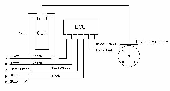
| Wiring and set up First locate the wire at the (+) connection on the coil this is the live feed from the ignition switch and will at some point have a ballast resistor fitted. Connect a new lead onto this wire and run it to the control box. Connect it to the black wire from the control box. Next identify the cranking feed from the starter motor or starter solenoid. This wire only becomes live when the engine is cranking over, it runs to the + on the coil bypassing the ballast resistor and supplies a full 12 volts to the original 7-volt coil to aid starting. Cut this wire and re route from the starter / solenoid to the black and green wire on the ignition module. Remember to tape over or blank off the other loose ends. The wire that was previously connected from the (-) on the coil to the distributor needs to be connected to the green wire on the ignition module. The brown, Green/Yellow and Black/Red are connected to earth and the distributor as shown in the drawing. To set up the timing you need to manually turn the engine until the timing mark on the front of the engine block is lined up with the 6 degrees before top dead centre mark on the front pulley and that the engine is on number one firing position. (Both number 1 cylinder valves shut) Best check with a Haynes manual if you're unsure of this. Also the BTDC may be different if you've converted unleaded. Next remove the distributor cap and make sure the rotor arm is lined up with number one plug lead. If its not you may have to remove the distributor, turn the rotor and refit. When it's in the right position partially tighten the retaining clamp. Now remove the rotor arm and cover plate and look at the position of the armature, the four teeth on the armature must be perfectly aligned with the four pins on the stator as shown in the photo. Carefully twist the distributor to achieve this. Fully tighten clamp plate and reassemble. Double check when refitting rotor arm that it is still aligned with no 1-plug lead. This should now be set well enough to start the engine. I then used a strobe light to finely tune the timing with the engine running. Finally I've purchased some non-adhesive loom tape from Frost Restorers Equipment Suppliers and taped up all the wires so that apart from the discreetly mounted ignition module you would hardly know that it wasn't all as original. The whole lot cost just Ł40 and I'll never have to fiddle with the points again. |